A crank handle is a practical part for learning Mastercam because it combines 2D profiling, pocketing, drilling, contouring, and basic machining strategy in one compact project. It typically includes a central hub, an offset arm, a handle boss, drilled holes, rounded ends, and chamfered edges, making it ideal for building confidence in CAD modeling and CAM workflow.
TLDR: A Mastercam crank handle tutorial usually begins with a clean 2D sketch, then moves into extrusion, hole creation, toolpath setup, verification, and machining. For example, a shop training class might reduce programming time by 30% when students follow a structured process using chained geometry, standard tool libraries, and simulation before posting code. The key is to keep geometry simple, select stable tools, and verify clearance before cutting metal.
Understanding the Crank Handle Design
The crank handle is commonly used as a training model because it has several recognizable machining features. A basic version includes a large circular hub at one end, a smaller circular boss at the other end, and a connecting arm between them. The hub may contain a central bore, while the handle end may include a smaller drilled or reamed hole.
In Mastercam, the designer usually starts with wireframe geometry. Circles define the hub and handle end, while tangent lines or arcs connect the two circles to create the arm. This approach gives better control over dimensions before converting the geometry into a solid or using it directly for toolpath chaining.
Image not found in postmetaStep 1: Creating the Base Geometry
The first stage is defining the part layout. A typical crank handle might have a hub diameter of 60 mm, a handle boss diameter of 35 mm, and a center distance of 120 mm. These numbers can vary, but the relationship between the two circles is what creates the recognizable crank shape.
- Set the units: The programmer should confirm whether the job uses millimeters or inches.
- Create the main hub: A circle is placed at the origin for easy setup and workholding alignment.
- Create the handle boss: A second circle is placed at the required offset distance.
- Add tangent lines: Tangent connections form the outer arm profile.
- Trim excess geometry: The final outline should be clean and chainable.
Clean geometry is important because broken chains, overlapping lines, and tiny gaps can cause toolpath errors. Before toolpath creation, the designer should use Mastercam’s analysis and trim tools to confirm that the profile is continuous.
Step 2: Building the Solid Model
Once the 2D outline is complete, the crank handle can be extruded to the desired thickness. For a training part, a thickness of 12 mm to 20 mm is common. The solid model helps with visualization, collision checking, and selecting faces for toolpaths.
The central hub may be made slightly thicker than the arm if the tutorial includes additional 3D features. However, many beginner-friendly versions use a flat plate style design to keep machining simple. Holes are then added through the hub and handle end using Mastercam’s solid hole tools or sketch-based circles.
A simple design is often better for training because it highlights toolpath quality rather than complex modeling.
Step 3: Planning the Machining Setup
Before assigning toolpaths, the programmer must define stock, work coordinate system, and machining origin. For a crank handle, rectangular stock is often selected because it is easier to clamp in a vise. The part can be centered on the stock with a small allowance around the outside profile.
A practical stock size might be 150 mm × 80 mm × 16 mm for a part that finishes at 140 mm long. This provides enough material for clamping and finishing passes. The origin is often placed at the center of the main hub or at the top-left corner of the stock, depending on shop preference.
Step 4: Choosing Tools
Tool selection depends on material, machine rigidity, and required finish. For aluminum, a common tool list may include:
- 6 mm or 1/4 inch end mill: Used for pocketing and rough profiling.
- 3 mm or 1/8 inch end mill: Used for smaller details or tight internal radii.
- Spot drill: Used to locate holes accurately.
- Twist drill: Used for through holes.
- Chamfer mill: Used to break sharp edges and improve appearance.
Feeds and speeds should be calculated based on cutter diameter, material, flute count, and spindle capability. In aluminum, a two-flute carbide end mill may run at relatively high spindle speed with moderate chip load. In steel, slower speeds and more conservative stepdowns are usually required.
Step 5: Creating Toolpaths in Mastercam
The crank handle usually begins with drilling operations. Spot drilling first prevents drill wander, especially on the central hub hole. Then the holes are drilled, bored, or reamed depending on tolerance requirements.
Next, pocketing may be used if the design includes recessed areas. For a simple flat crank handle, the main operation is the outside contour. The programmer chains the outer profile and assigns the end mill, compensation direction, depth cuts, and lead-in/lead-out moves.
Image not found in postmetaFor reliable contouring, the toolpath should include:
- Roughing pass: Leaves a small amount of stock, such as 0.2 mm or 0.01 inch.
- Finishing pass: Removes the remaining stock for a smoother edge.
- Tabs or bridges: Hold the part in place if it is cut from flat stock.
- Safe retracts: Prevent the tool from dragging across clamps or stock.
Tabs are particularly useful when machining the entire outer profile. Without them, the part may shift as it breaks free, damaging the cutter or leaving marks on the finished edge.
Step 6: Verifying and Backplotting
Simulation is one of the most important steps in a Mastercam crank handle tutorial. Backplot shows tool movement, while Verify displays material removal. The programmer should check for rapid moves through stock, incorrect depth settings, gouges, and missed geometry.
A good verification routine includes reviewing each operation individually, then running the entire program from start to finish. If the software shows leftover material along the profile, the tool diameter, chain direction, or stock allowance may need adjustment.
Machining Tips for Better Results
Several practical habits can improve the final crank handle and reduce setup mistakes:
- Use climb milling for finishing: It often produces a cleaner edge on CNC mills.
- Leave finish stock: A light final pass improves dimensional accuracy and surface finish.
- Check tool stickout: Shorter stickout reduces chatter and improves rigidity.
- Deburr between operations: Burrs can affect inspection and secondary setups.
- Use coolant or air blast: Chip evacuation is critical, especially in pockets and profiles.
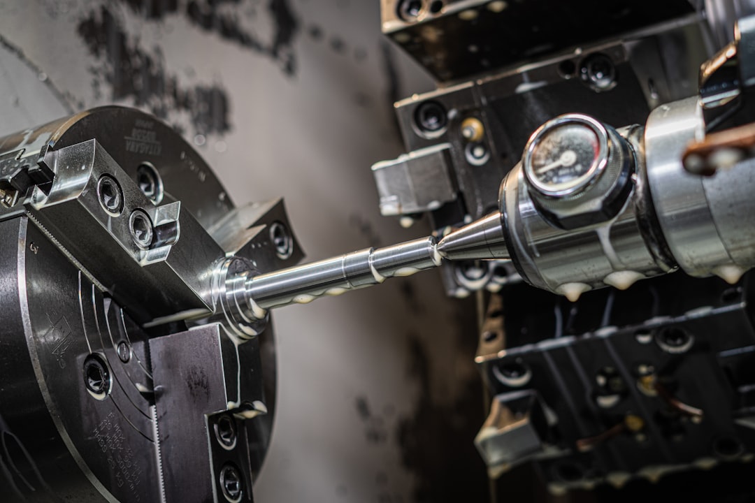
If the crank handle is made from aluminum, chip welding can occur when tools are dull or coolant is insufficient. If it is made from mild steel, chatter and tool deflection may be more noticeable. In both cases, conservative roughing and a dedicated finishing pass will usually produce better results than one aggressive cut.
Common Mistakes to Avoid
Beginners often make mistakes with chain direction, compensation, and depth settings. If compensation is set to the wrong side, the tool may cut inside the profile instead of outside. If the final depth is incorrect, the part may not separate from the stock or may cut into the fixture.
Another common issue is forgetting to account for the tool radius in internal corners. A crank handle with sharp inside transitions cannot be machined perfectly with a round cutter unless relief radii are added. The designer should include realistic radii that match available tools.
Final Inspection
After machining, the crank handle should be inspected for overall length, hole diameter, thickness, and edge quality. A caliper can check general dimensions, while pins or gauges can verify hole sizes. The finished part should rotate or mount correctly if it is part of an assembly.
The final result is not only a physical component but also a complete programming exercise. It teaches the connection between design intent, toolpath strategy, machine setup, and inspection.
FAQ
What Mastercam skills are learned from a crank handle tutorial?
It teaches 2D sketching, chain selection, drilling, contouring, stock setup, simulation, and post-processing.
Is a crank handle better as a 2D or 3D project?
For beginners, it is usually better as a 2D machining project. Advanced users can add 3D fillets, bosses, or sculpted surfaces.
What material is best for practice?
Aluminum is often preferred because it machines quickly, produces good finishes, and is forgiving for training.
Why are tabs used when cutting the outside profile?
Tabs keep the part attached to the stock so it does not move during the final contour pass.
Should the holes be machined before the outside profile?
Yes. Drilling holes first is usually safer because the stock is still rigid and fully supported.
What is the most important machining tip for this part?
The most important tip is to verify the program before machining. Simulation helps prevent crashes, incorrect depths, and profile errors.